|
BigCam |
|
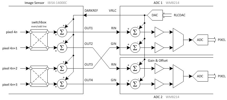
A pair of WM8214 ADCs samples the image sensor's output signal. The WM8214 is a 16-bit, 40MSPS converter that can switch between 1, 2 or 3 input channels; since the sensor produces 4 outputs at 15MSPS each, two converters operating in 2-channel mode are required.
The ADC inputs connect directly to the image sensor outputs. The image sensor has a quite flexible output stage; a pin called DARKREF sets the "base" level (typically about 2.65V), and the four outputs swing from DARKREF to DARKREF-1.2V depending on light level. This arrangement is very convenient. The voltage on WM8214's pin VRLC is subtracted from the input voltage on each sample, and there is an optional 4-bit DAC that allows WM8214 to drive VRLC with a configurable voltage as well. Therefore, DARKREF on the sensor is connected to both ADCs' VRLC pins, and one of the ADCs drives it at 2.6-2.65V. The difference between the video signal and DARKREF/VRLC is always negative. WM8214 supports this mode (negative going video) and can be configured to output code 0x0000 for VIN = VRLC and 0xFFFF for VIN = VRLC-1.2V. In other words, the analog interface is entirely glueless. WM8214 also contains analog gain and offset registers, which allows BigCam to configure the light sensitivity and trim out the dark current even before analog to digital conversion. To reduce the difference between subsequent values digitized by each ADC, the sensor's internal switchboxes are set up so that all green samples appear on odd-numbered outputs (OUT1 and OUT3), and all red/blue samples appear on even-numbered outputs (OUT2 and OUT4). Since a row of a Bayer array contains red/green or green/blue outputs only, each ADC is effectively dedicated to red, green or blue pixels for the whole row. |
(c) 2011 Stanislaw Skowronek
Contact me: skylark unaligned org (figure out where to put the @ and .)